Pipe Reducer Selection Guide: Concentric vs Eccentric Design and Application Criteria
2026-05-27 16:52:04
The pipe reducer, a deceptively simple component that transitions between different pipe diameters, plays a crucial role in managing flow velocity, pressure drop, and system flexibility in industrial piping networks. Available in two primary geometries—concentric and eccentric—these fittings must be selected based on fluid characteristics, space constraints, and mechanical considerations specific to each installation. Manufacturing facilities specializing in pipe fittings, particularly those in Hebei's Cangzhou industrial corridor, produce reducers to exacting dimensional tolerances specified in ASME B16.9, MSS SP-75, and equivalent international standards, serving industries from water treatment to hydrocarbon processing.

Concentric Reducer Geometry and Flow Characteristics
The concentric reducer, featuring a centrally aligned inlet and outlet, provides symmetrical flow contraction or expansion. This geometry proves advantageous in vertical piping runs where air or gas pockets must be avoided, as the symmetrical shape prevents flow separation and minimizes turbulence generation. The gradual reduction in cross-sectional area increases fluid velocity while raising static pressure according to Bernoulli's principle, effects that must be accounted for in pump suction and discharge line designs to prevent cavitation or excessive NPSH requirements.
From a manufacturing perspective, concentric reducers can be produced through multiple methods including seamless pipe extrusion, plate pressing, or segmental welding. Seamless manufacturing, wherein a heated pipe blank is hydraulically expanded while simultaneously compressed to form the reduced section, yields superior metallurgical integrity and is preferred for high-pressure or corrosive services. The extrusion process maintains grain flow continuity through the transition section, enhancing both mechanical strength and resistance to stress corrosion cracking. Reputable reducer suppliers provide material traceability documentation and optional non-destructive testing to verify internal soundness.
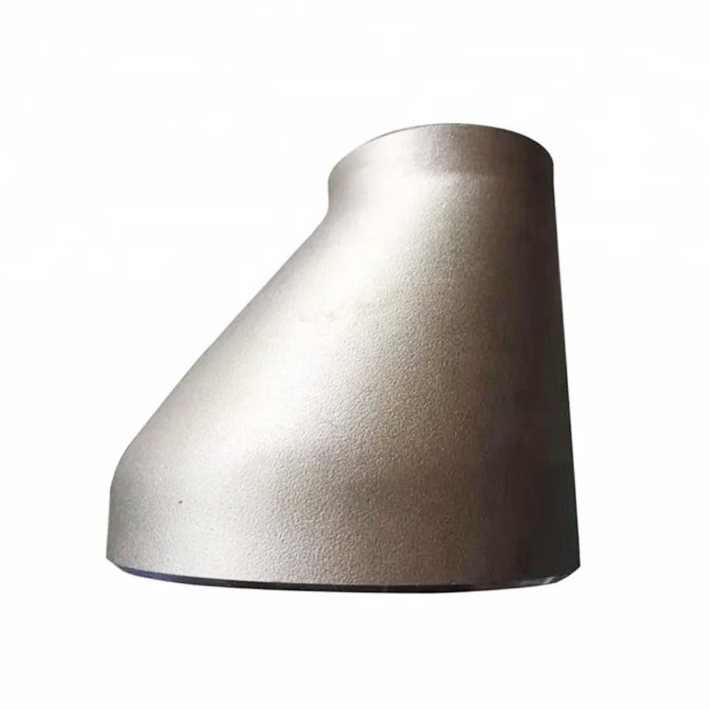
Eccentric Reducer Applications and Flat-Side Orientation
Unlike its concentric counterpart, the eccentric reducer incorporates an offset centerline between inlet and outlet, creating a fitting with one flat side when viewed in elevation. This geometry becomes essential in horizontal piping systems where maintaining pipe bottom elevation (on-grade alignment) or top elevation (top-of-pipe alignment) is necessary for drainage, instrumentation connectivity, or structural support continuity. The flat side orientation—whether installed with the flat on top, bottom, or side—depends entirely on the specific piping routing requirements and must be clearly indicated on isometric drawings to prevent field installation errors.
In pump suction applications, eccentric reducers are universally specified with the flat side up (top flat) to prevent air pocket formation that could lead to cavitation and pump damage. Conversely, gravity drainage systems typically require the flat side down (bottom flat) to ensure complete liquid evacuation without creating low-velocity zones where solids might settle. The fabrication of eccentric reducers, particularly for large diameters or thick walls, often employs plate rolling and welding techniques, necessitating rigorous weld inspection and dimensional verification before shipment from the manufacturing facility.
Material Selection and Corrosion Allowance Considerations
Reducer material selection follows the same metallurgical principles governing other piping components, with additional consideration for potential erosion at the diameter transition. Carbon steel reducers (ASTM A234 WPB) suffice for ambient-temperature, non-corrosive services, while stainless steel grades (304, 316, 321, 347) address general corrosion concerns in chemical, food, and pharmaceutical applications. For abrasive slurry services, specifying reducers with enhanced wall thickness—typically schedule 80 or schedule 160 even when adjacent piping is standard weight—extends service life by providing additional material to withstand erosion-corrosion mechanisms.
Alloy steel reducers, including those manufactured from A234 WP11, WP22, and WP91 materials, provide the high-temperature strength necessary for steam systems, refinery process units, and power generation facilities. These materials require controlled heat treatment—normalizing, quenching and tempering, or stress relieving depending on grade and application—to achieve specified mechanical properties. Responsible manufacturers maintain heat treatment furnaces with calibrated temperature recording systems, ensuring that each production batch receives proper thermal processing documented in the material test report accompanying the shipment.
Dimensional Standards and Custom Fabrication Options
While ASME B16.9 defines standard reducer dimensions for nominal pipe sizes from 1/2 inch through 48 inches, industrial projects frequently demand non-standard configurations. Custom reducers, fabricated to accommodate specialized process requirements, may feature non-standard length-to-diameter ratios, transition between different pipe schedules, or incorporate reinforced sections for structural loading. Chinese pipe fitting factories, equipped with sophisticated plate rolling equipment and welding systems, regularly produce custom reducers to client specifications, providing detailed fabrication drawings and inspection test plans (ITP) for project approval.
For large-diameter applications exceeding standard manufacturing capabilities, site fabrication or specialized workshop assembly becomes necessary. In such cases, reducers may be fabricated from plate material using segmental construction, with weld joints positioned to minimize stress concentrations and facilitate non-destructive testing. The quality assurance program for custom reducers must address not only dimensional accuracy but also weld procedure qualifications, heat treatment documentation, and surface finish requirements specific to the service environment. Experienced suppliers guide project teams through the specification process, ensuring that custom reducers satisfy both performance requirements and applicable code obligations.
References
ASME B16.9 - Factory-Made Wrought Buttwelding Fittings
ASME B31.1 - Power Piping Code
ASME B31.3 - Process Piping Code
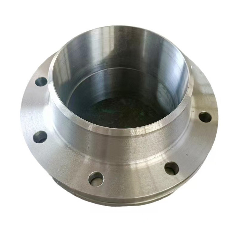
AWeld Neck Flange (WN Flange)is a type of piping flange designed to be welded to a pipe or ...
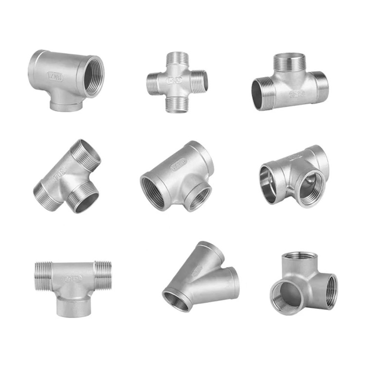
Socket fittings are essential components in piping systems, designed to connect, branch, or...
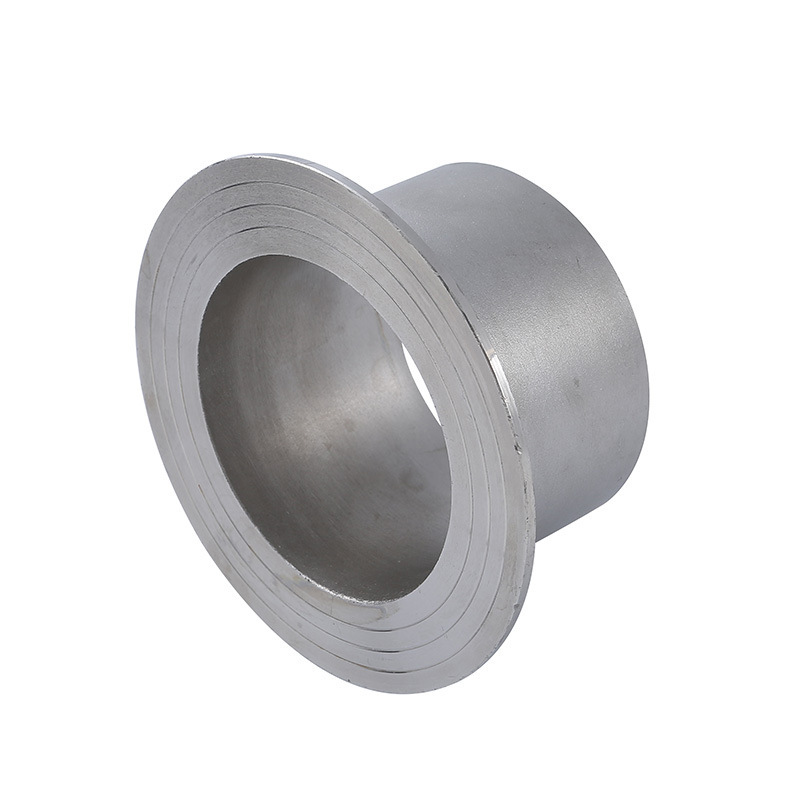
Welding ring is a commonly used metal ring component in pipeline connection or equipment do...
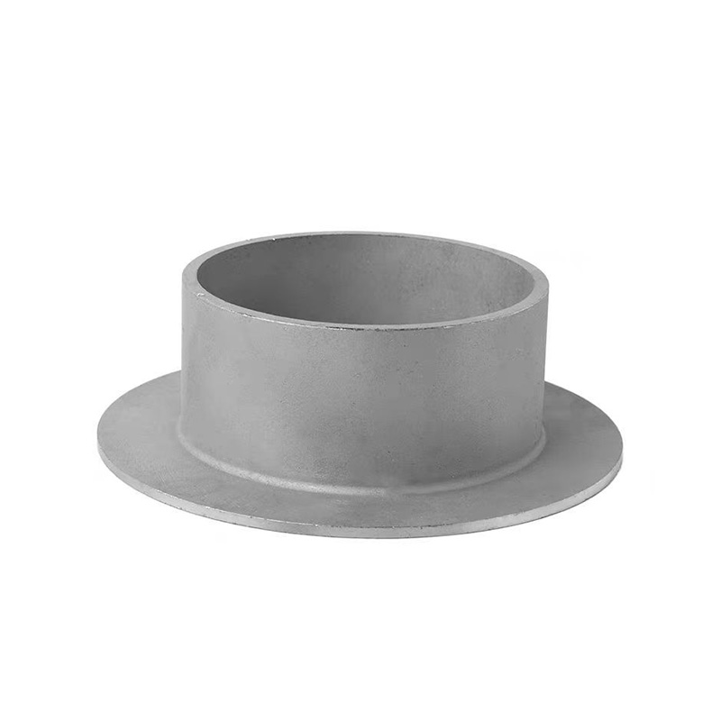
Welding ring is a pipe fitting used for pipeline connection. The following is its detailed ...