Understanding Pipe Flange Types and Face Styles: A Practical Guide
2026-09-02 17:25:58
Flanges are the connection points where pipelines meet equipment, valves, and each other. Get the flange right and your system assembles cleanly, seals reliably, and stays maintenance-free. Get it wrong and you deal with leaks, bolt failures, and schedule delays from the moment you pressurize the system.
This guide covers the flange types you will encounter in industrial applications, the face styles that determine sealing performance, and the practical factors that drive selection decisions.
The Major Types of Industrial Flanges
Weld Neck Flange
The weld neck flange features a long, tapered hub that transitions
smoothly from the pipe bore to the flange face. The hub is butt-welded
to the pipe, creating a joint with strength approaching that of the pipe
itself. This design distributes stress effectively, making weld neck
flanges the preferred choice for high-pressure, high-temperature, and
fatigue-critical applications such as refinery piping, steam systems,
and offshore platforms. The initial cost is higher than other types, but
the superior joint integrity reduces long-term risk.
Slip-On Flange
Slip-on flanges slide over the pipe and are welded both inside and
outside the circumference. They are easier to align during installation
than weld neck flanges and require less precise pipe preparation.
However, the welded connection is less strong and the flange hub adds
some flow obstruction. Slip-on flanges are common in low-pressure water
systems, HVAC ducting, and utility piping where cost matters more than
maximum pressure rating.
Blind Flange
A blind flange has no center hole — it seals the end of a pipe run or
vessel nozzle. Blinds are used to close a pipeline for future expansion,
to facilitate pressure testing, or to provide access points for
inspection. They carry the same pressure rating as the piping system
they serve. When selecting a blind flange, consider whether you need a
full-face gasket or a ring-type gasket based on your existing flanges.
Socket Weld Flange
Socket weld flanges have a socket or bore that receives the pipe, which
is then fillet-welded around the outside. The internal weld fillet adds
strength, though the connection is not as robust as a butt-weld joint.
Socket weld flanges are typically limited to small-bore piping,
generally NPS 4 and smaller, in high-pressure service.
Threaded Flange
Threaded flanges have internal threads that screw onto a matching
external-threaded pipe. No welding is required, which simplifies
installation in situations where welding is impractical — underground
piping, temporary connections, or hazardous-area work. The threaded
connection limits maximum pressure and temperature ratings, so threaded
flanges are most common in low-pressure water, air, and fire protection
systems.
Lap Joint Flange
Lap joint flanges do not make a seal themselves — they rotate freely
around a stub end that is welded to the pipe. The gasket sits between
the flange face and the mating surface. This design allows quick
assembly and disassembly without rotating the pipe. Lap joint flanges
are used where frequent inspection or cleaning requires access, such as
in food processing, pharmaceutical, and pulp and paper systems.
Flange Face Styles: Getting the Sealing Surface Right
The face of the flange — the surface that contacts the gasket — comes in several profiles, each designed for different sealing requirements.
Raised Face (RF)
The raised face flange has a concentric ring raised approximately 1.6mm
(1/16 inch) above the flange bore. This raised surface concentrates bolt
load on a smaller area, improving gasket compression and creating a
more reliable seal. Raised face flanges are the most common type in
modern industrial piping systems worldwide. Spiral-wound or ring gaskets
typically accompany them.
Flat Face (FF)
Flat face flanges have no raised surface — the entire face is level.
They are used in applications where the mating flange or equipment
surface is also flat, such as cast iron valve bodies or equipment with
flat-face flanges. Using a raised face flange against a flat face flange
risks cracking the cast iron component due to uneven loading.
Ring-Type Joint (RTJ)
Ring-type joint flanges have a circular groove machined into the face to
receive a metal ring gasket. The gasket seats in the groove under bolt
pressure, creating a metal-to-metal seal that handles extremely high
pressures and temperatures. RTJ flanges are standard in oil and gas
production, high-pressure chemical plants, and steam systems. The ring
gasket must match the groove dimensions exactly — mixing gasket types
causes immediate leakage.
Tongue and Groove (T&G)
Tongue and groove facings feature a raised tongue on one flange and a
matching groove on the other. This self-centering design provides
precise alignment and contains the gasket under pressure. T&G
facings see use in low-pressure, high-vacuum, or sanitary applications
where alignment and containment are priorities.
Common Standard Specifications
Different standards govern flange dimensions, pressure ratings, and materials depending on where you are in the world:
ASME B16.5 — Covers pipe flanges and flanged fittings for NPS 1/2 through NPS 24 in pressure ratings from Class 150 to 2500. The dominant standard in North America and many international projects.
ASME B16.47 — Large-diameter steel flanges for NPS 26 through NPS 60. Divided into Series A (MSS SP-44) and Series B (API 605).
EN 1092-1 — European standard covering steel flanges for a wide range of pressure ratings, using PN designations instead of class ratings.
DIN 2501 — Older German standard, still referenced in many existing plant specifications.
JIS B2220 — Japanese standard for steel pipe flanges, commonly used in Southeast Asian markets and Japanese-influenced projects.
Pressure Classes vs. PN Ratings
Flanges are rated by pressure class (ASME system) or nominal pressure (PN, European system). A Class 300 flange has a higher pressure rating than a Class 150 flange of the same size, but the relationship is not linear — the Class 300 rating increases faster at lower temperatures and may converge at elevated temperatures.
Always select the pressure class based on your maximum operating pressure at the maximum operating temperature. Never assume a Class 300 flange is simply "better" than a Class 150 — the bore dimensions and bolt patterns differ, and mismatched flanges cannot be joined.
Materials and Corrosion Resistance
Flange material must be compatible with the service fluid and environment. Common materials include:
Carbon steel (ASTM A105) — Standard for general-purpose high-temperature service. Requires coating or painting for corrosive environments.
Stainless steel (ASTM A182 F304/F316) — Excellent corrosion resistance. 316 is preferred for chloride-containing environments.
Alloy steel (ASTM A182 F11, F22) — Higher chromium content for elevated temperature service in power and process plants.
Duplex stainless steel (ASTM A182 F51/F53) — Combines austenitic and ferritic microstructure for superior strength and chloride resistance.
Installation Considerations
Even the highest-quality flange will leak if installed incorrectly. Key practices include:
Inspect flange faces for damage, rust, or gasket debris before assembly
Use the correct gasket type and material for your service conditions
Align flanges before inserting bolts — never force misaligned flanges together
Tighten bolts in a crosswise pattern to distribute load evenly
Use calibrated torque wrenches for critical applications to achieve proper bolt stress
Re-torque bolts after initial heat-up for high-temperature flanged joints
Conclusion
Understanding flange types and face styles is essential for specifying the right component for your system. Weld neck flanges handle the most demanding applications; slip-on flanges offer economy where conditions allow. Raised face is the default for modern industrial work; RTJ facings are mandatory for extreme pressure-temperature combinations.
Always match your flange standard, pressure class, and material to your system design, and source from a supplier with proper mill certifications and traceability documentation. A few minutes of careful specification now prevents hours of leak-chasing later.
References
References:
ASME B16.5-2017, Pipe Flanges and Flanged Fittings NPS 1/2 Through NPS 24, The American Society of Mechanical Engineers
API 600-2015, Bolted Bonnet Gate Valves for Petroleum and Natural Gas Industry, American Petroleum Institute
EN 1092-1:2018, Flanges and their joints — Circular flanges for pipes,
valves, fittings and accessories, European Committee for Standardization
MSS SP-44-2019, Steel Pipe Line Flanges, Manufacturers Standardization Society
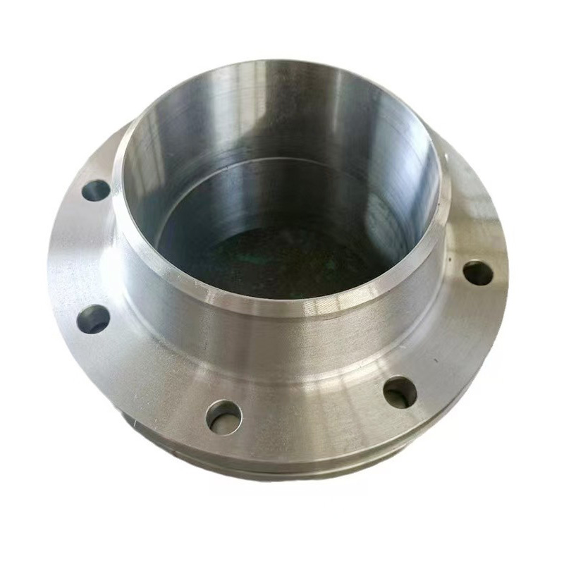
AWeld Neck Flange (WN Flange)is a type of piping flange designed to be welded to a pipe or ...
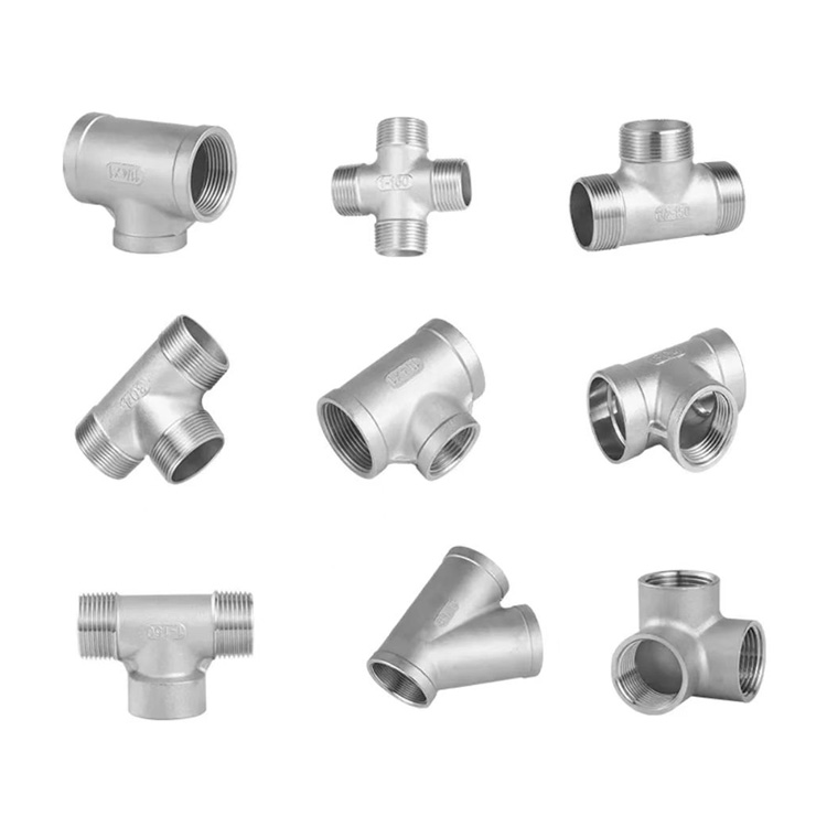
Socket fittings are essential components in piping systems, designed to connect, branch, or...
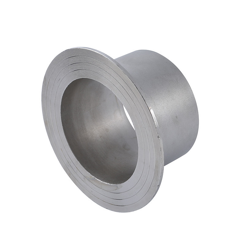
Welding ring is a commonly used metal ring component in pipeline connection or equipment do...
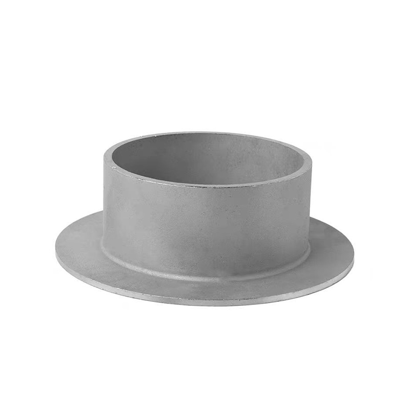
Welding ring is a pipe fitting used for pipeline connection. The following is its detailed ...