Pipe Reducer Types and Applications: Concentric vs Eccentric Explained
2026-09-05 17:37:58
Pipeline systems rarely maintain a single pipe size from start to finish. Equipment connections, flow requirements, and cost optimization all drive changes in pipe diameter along a pipeline. The reducer is the component that manages those transitions — and choosing between a concentric and eccentric reducer can have real consequences for how your system performs.
This article explains the two main reducer types, their practical differences, common applications, and the key considerations when specifying reducers for industrial projects.
What Is a Pipe Reducer?
A pipe reducer is a fitting that connects two pipes of different diameters. It is classified as a fitting that reduces the nominal pipe size, allowing the pipeline to transition from a larger diameter to a smaller diameter (or vice versa). The reduction can be gradual or abrupt, depending on the reducer design.
Reducers create two important changes in a piping system: a change in flow velocity and a change in pressure. As pipe diameter decreases, fluid velocity increases if the flow rate remains constant. This has implications for pumping costs, erosion rates, and system design.
Concentric Reducers
A concentric reducer maintains a continuous centerline through the fitting. Both the large and small ends are aligned on the same axis, creating a symmetrical transition that looks like a truncated cone. The flow path through a concentric reducer is smooth and unimpeded, with no disruption to the fluid stream.
Advantages of concentric reducers:
Symmetrical design means no flow disturbance when installed horizontally
Smooth interior transition minimizes pressure loss
Simpler manufacturing process, generally lower cost than eccentric reducers
Self-cleaning design prevents solids accumulation in vertical installations
Common applications:
Vertical pipelines where flow direction is downward (gravity-assisted)
Horizontal pipelines with no solids settling concerns
General process piping where flow uniformity is maintained
Pump suction lines with vertical orientation
Eccentric Reducers
An eccentric reducer offsets the centerlines of the large and small ends, creating a flat-sided transition. The offset can be on the top or bottom of the fitting, depending on installation requirements. This design eliminates the offset in pipe elevation that would otherwise occur when connecting misaligned pipes.
Advantages of eccentric reducers:
Maintains a flat bottom alignment when installed with the flat side down — critical for pipelines conveying fluids with entrained solids
Prevents air accumulation at the transition point when installed flat-side up
Minimizes flow disturbance for certain pump suction configurations
Allows smoother transition between pump suction and smaller-diameter suction piping
Common applications:
Horizontal pipelines carrying slurry, pulp, or fluids with suspended solids
Horizontal pump suction lines — eccentric reducers with flat side up minimize air entrainment
Pipelines where the top of the pipe must remain at a consistent elevation
Steam and condensate return lines where water accumulation must be avoided
Eccentric Reducer: Flat Side Up or Down?
This is one of the most commonly misunderstood aspects of eccentric reducer installation. The orientation matters depending on the application:
Flat side down — Used in most horizontal pipelines carrying fluids with entrained solids. The flat bottom prevents solids from settling at the reduction point and creating a buildup that could eventually block the pipe. This is the default installation orientation for slurry lines, wastewater systems, and pulp processing.
Flat side up — Used specifically in pump suction piping. When a pump draws from a horizontal pipe with a smaller branch, air can become trapped at the top of the reducer if it is installed flat-side down. Installing with the flat side up allows any entrained air to flow through and be expelled from the system rather than accumulating at the reducer and causing cavitation in the pump.
Always confirm the required orientation with your piping engineer before installation. Mixing up the orientation can create serious operational problems.
Sizing and Dimensions
Reducers are sized by the nominal pipe size at each end. A typical specification looks like: "8 x 4 butt weld concentric reducer, Schedule 40." This indicates the reducer connects an 8-inch NPS pipe to a 4-inch NPS pipe, with the wall thickness matching Schedule 40 pipe.
Reducing reducers are available in standard reduction increments. Common reductions include 2:1 (8" to 4", 6" to 3", 4" to 2") and 1.5:1 (6" to 4", 4" to 2.5"). Larger or more unusual reductions may require custom fabrication from pipe or plate.
The length of a reducer — the distance between the large and small ends — varies by standard. ASME B16.9 specifies a standard center-to-end dimension based on the larger size. Custom lengths are available from most manufacturers for special layout requirements.
Pressure Drop Through Reducers
Any change in pipe diameter causes some pressure loss due to turbulence and friction at the transition. The pressure drop depends on:
Size ratio — Larger reductions cause greater pressure loss. A gradual 2:1 reduction has less loss than an abrupt 4:1 reduction.
Flow velocity — Higher flow rates through the same reducer create proportionally higher pressure losses.
Reducer geometry — Long-radius reducers (with a gradual taper) create less turbulence than short-radius or multi-step reducers.
For most process applications, the pressure drop through a standard reducer is calculated using industry-standard formulas or software. In pump system design, reducer pressure loss must be included in the total system head calculation to ensure the pump is properly sized.
Manufacturing Methods
Seamless reducers are formed from a single piece of steel — either hot-pushed from a seamless pipe shell or cold-formed. Seamless construction is preferred for high-pressure applications where weld seam integrity is a concern.
Welded reducers are fabricated from steel plate, formed into cones, and welded along the longitudinal seam. Modern welding with automated equipment produces consistent, high-quality seams. Welded reducers are economical for large-diameter applications and are widely used in water distribution, oil and gas transmission, and construction.
Swaged reducers are made by mechanically reducing the end of a pipe section to the desired smaller diameter using a swaging machine. This method is efficient for short-run production and specific size combinations.
Material Options
Reducers are available in the same material grades as other pipe fittings:
Carbon steel (ASTM A234 WPB) for general purpose high-temperature service
Stainless steel (ASTM A403 304/316) for corrosive environments
Alloy steel (ASTM A234 WP11, WP22) for elevated temperature power and process applications
Duplex stainless steel for chloride-rich environments requiring high strength
Match the reducer material to the pipe material in your system to avoid galvanic corrosion and ensure consistent thermal expansion behavior.
Key Takeaways for Buyers and Engineers
Use concentric reducers as the default choice for vertical pipelines and horizontal pipelines without solids
Use eccentric reducers flat-side down for horizontal slurry and solid-carrying pipelines
Use eccentric reducers flat-side up for pump suction piping
Specify reducers by both NPS ends, schedule (wall thickness), and connection type (butt weld, socket weld, threaded)
Request material test certificates to verify grade compliance
Consider pressure drop calculations for high-flow or long-distance pipeline systems
Conclusion
Both concentric and eccentric reducers serve essential roles in industrial piping. The choice between them comes down to the application: solids settling concerns push toward eccentric flat-side-down; pump suction requires eccentric flat-side-up; general process use defaults to concentric. Getting the orientation wrong on an eccentric reducer can create serious operational problems — so specification and communication with the installation team matter.
Working with an experienced reducer manufacturer who understands these distinctions helps ensure the right fitting arrives on site, properly documented and ready for installation.
References
References:
ASME B16.9-2018, Factory-Made Wrought Buttwelding Fittings, The American Society of Mechanical Engineers
ASME B31.3-2022, Process Piping, The American Society of Mechanical Engineers
ISO 3419:1981, Steel buttwelding fittings other than castings and forgings, International Organization for Standardization
Hydraulic Institute Standards for Centrifugal, Rotary and Reciprocating Pumps, Hydraulic Institute
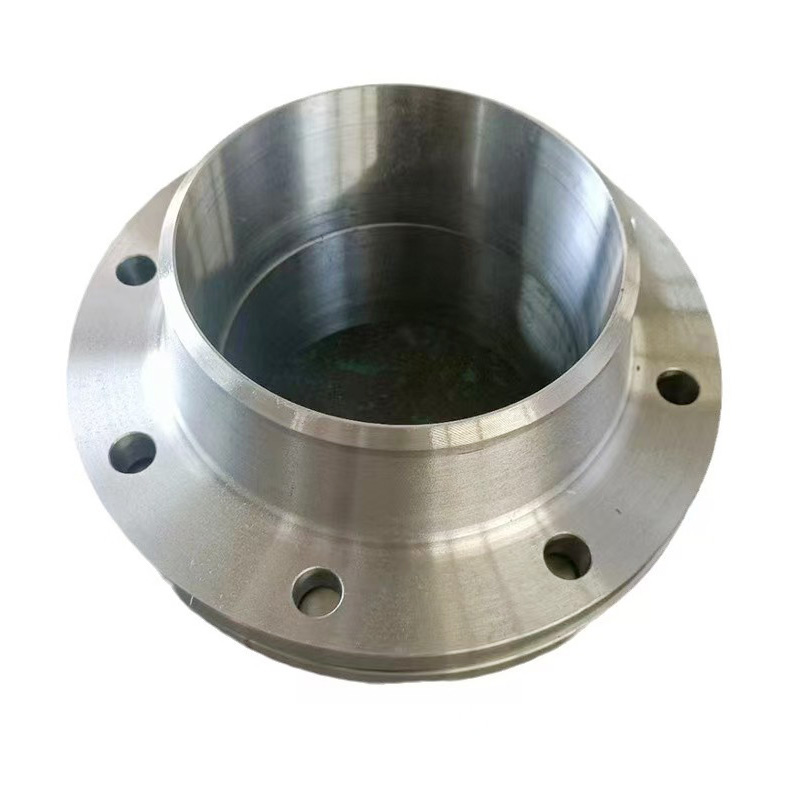
AWeld Neck Flange (WN Flange)is a type of piping flange designed to be welded to a pipe or ...
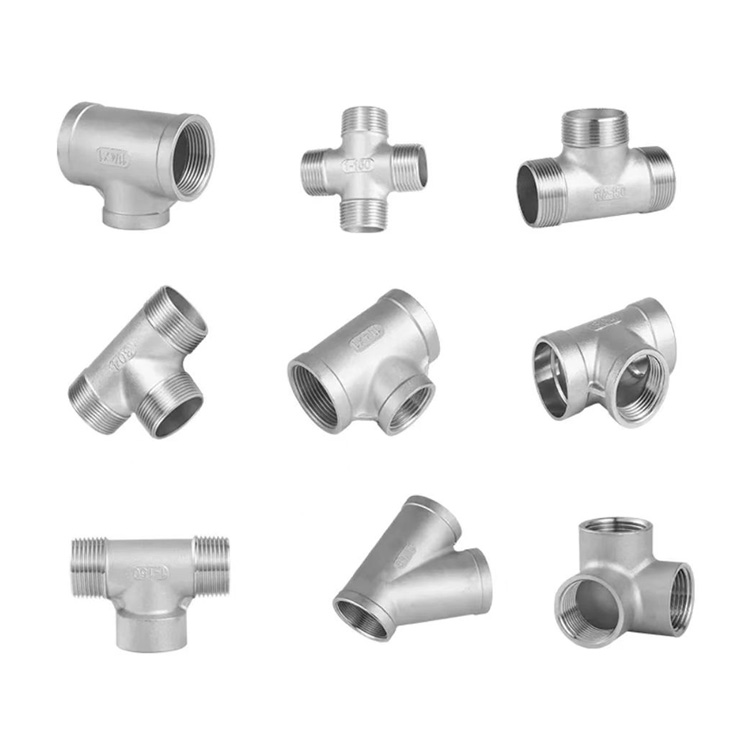
Socket fittings are essential components in piping systems, designed to connect, branch, or...
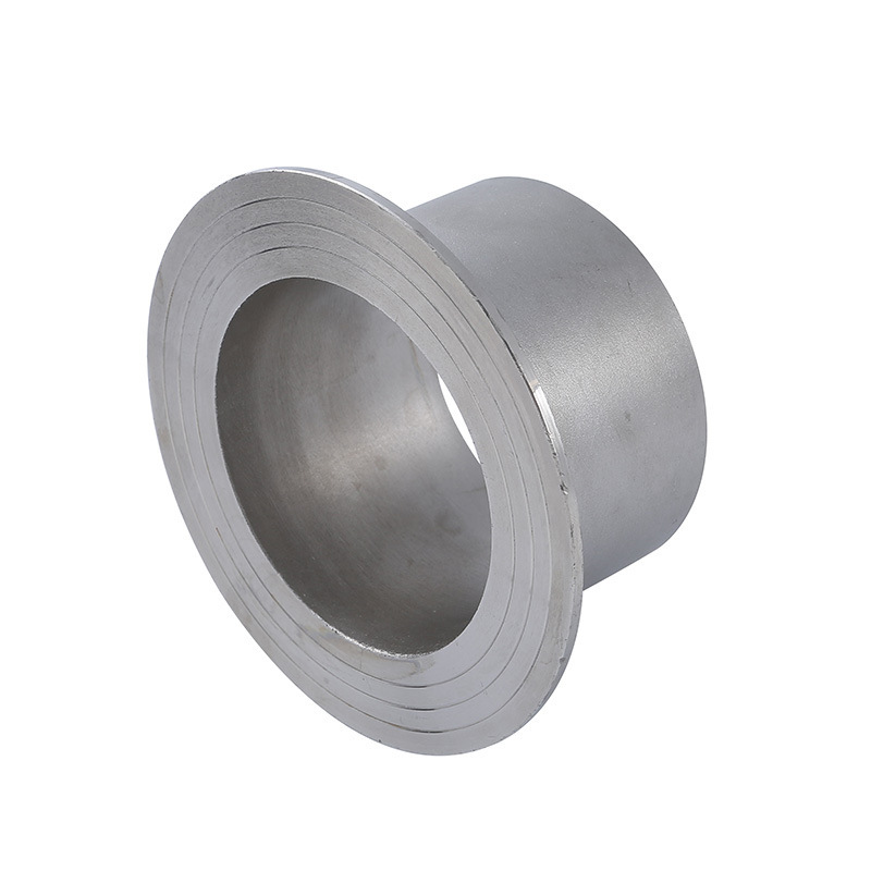
Welding ring is a commonly used metal ring component in pipeline connection or equipment do...
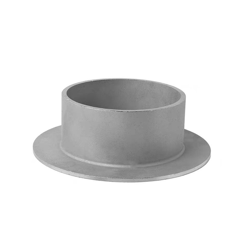
Welding ring is a pipe fitting used for pipeline connection. The following is its detailed ...