Weld Neck Flange Technical Specifications and Selection Guide
2026-06-05 17:54:08
The weld neck flange, distinguished by its tapered hub that transitions smoothly to the pipe wall thickness, represents the premium connection choice for high-pressure, high-temperature, and cyclic loading applications. Unlike slip-on or socket weld alternatives, the weld neck design provides excellent stress distribution characteristics, making it indispensable in refineries, power plants, and offshore platforms where joint integrity directly impacts operational safety. Manufacturing facilities in Hebei's Cangzhou region, equipped with advanced forging presses and precision machining centers, produce these critical components to meet diverse international standards including ASME, DIN, JIS, and BS specifications.

Pressure-Temperature Ratings and Class Designations
Flange selection begins with understanding the pressure-temperature (PT) rating system, which defines the allowable working pressure at various temperatures for different material groups. ASME B16.5 class designations—150, 300, 400, 600, 900, 1500, and 2500—represent pressure-temperature ratings rather than direct pressure limitations. A Class 300 flange, for instance, is rated for 740 psi at 100°F but only 565 psi at 500°F for A105 carbon steel. This derating reflects the temperature-dependent strength reduction in metallic materials, a fundamental consideration that flange suppliers must communicate clearly to project engineers during the specification phase.
Beyond ASME standards, European projects frequently reference DIN 2631-2635 or EN 1092-1 flange standards, which employ PN (pressure nominal) designations such as PN10, PN16, PN25, PN40, and PN63. The conversion between ASME Class and DIN PN ratings is approximate rather than exact, requiring careful verification when sourcing flanges for multinational projects. Reputable flange factories maintain dual certification capabilities, enabling supply of both ASME and EN-standard flanges from the same production facility, thereby streamlining procurement for global EPC contractors.
Hub Design and Stress Distribution Analysis
The defining characteristic of a weld neck flange—its tapered hub—serves a critical engineering function: gradual transition of wall thickness from the flange to the pipe. This geometric feature reduces stress concentration at the weld joint, where abrupt geometry changes in slip-on flanges create vulnerability to fatigue failure under cyclic loading. Finite element analysis studies demonstrate that weld neck flanges exhibit 30-40% lower stress intensification factors compared to slip-on designs, justifying their specification in vibrating equipment connections, thermal cycling services, and critical process lines.
The hub length, standardized at approximately 2.5 inches for standard weight pipe in ASME B16.5, must be matched to the pipe schedule to ensure proper weld preparation. Field welding procedures should specify complete joint penetration (CJP) welds with appropriate bevel angles, typically 37.5° ± 2.5° per ASME B16.5 recommendations. Post-weld heat treatment (PWHT) may be required depending on the material combination, section thickness, and applicable code requirements—considerations that responsible flange manufacturers address through comprehensive material test reports and welding procedure qualifications.
Facing Types and Surface Finish Requirements
The sealing surface of a weld neck flange, technically termed the "facing," must be selected to match gasket specifications and service conditions. Raised face (RF) flanges, featuring a concentric raised surface surrounding the bore, accommodate soft gaskets and represent the default choice for most services below 900 psi and 500°F. The raised face height, standardized at 1/16 inch for Class 150/300 and 1/4 inch for Class 400 and above, ensures proper gasket compression without excessive bolt loading.
Ring-type joint (RTJ) facings, incorporating a precision-machined groove to accept metallic ring gaskets, serve high-pressure applications where soft gasket materials cannot maintain seal integrity. The oval or octagonal cross-section ring gaskets, typically manufactured from soft iron, low carbon steel, or stainless steel depending on service conditions, achieve metal-to-metal sealing through controlled plastic deformation. Surface finish on RTJ grooves requires exceptional precision, with roughness typically specified at 63 microinches (1.6 micrometers) Ra maximum to prevent leakage paths. Flange machining facilities employing CNC equipment achieve these tolerances consistently, ensuring interchangeability and reliable sealing performance.
Material Selection for Corrosive and Elevated Temperature Services
Carbon steel flanges (A105, A350 LF2) suffice for ambient temperature, non-corrosive services, but process environments frequently demand upgraded material grades. Stainless steel flanges—304, 316, 321, 347, and their L-grades—address general corrosion concerns, while alloy steels such as F11, F22, and F91 provide the creep strength necessary for high-temperature steam and process applications. The selection must consider not only the flange material but also its compatibility with adjacent piping and fasteners to prevent galvanic corrosion or differential thermal expansion issues.
For extreme corrosive environments, exotic alloy flanges including Monel, Inconel, Hastelloy, and titanium find application despite their substantial cost premium. These materials, often supplied as custom-forged components from specialized manufacturers, require careful handling throughout the supply chain to prevent iron contamination that could compromise corrosion resistance. Material traceability from melt shop to finished flange, documented through mill test reports and heat stamps, provides essential quality assurance for critical service applications where flange failure carries significant safety and environmental risks.
References
ASME B16.5 - Pipe Flanges and Flanged Fittings
ASME B16.47 - Large Diameter Steel Flanges
EN 1092-1 - Flanges and their joints - Circular flanges for pipes, valves, fittings and accessories
API 6A - Specification for Wellhead and Christmas Tree Equipment
MSS SP-44 - Steel Pipeline Flanges
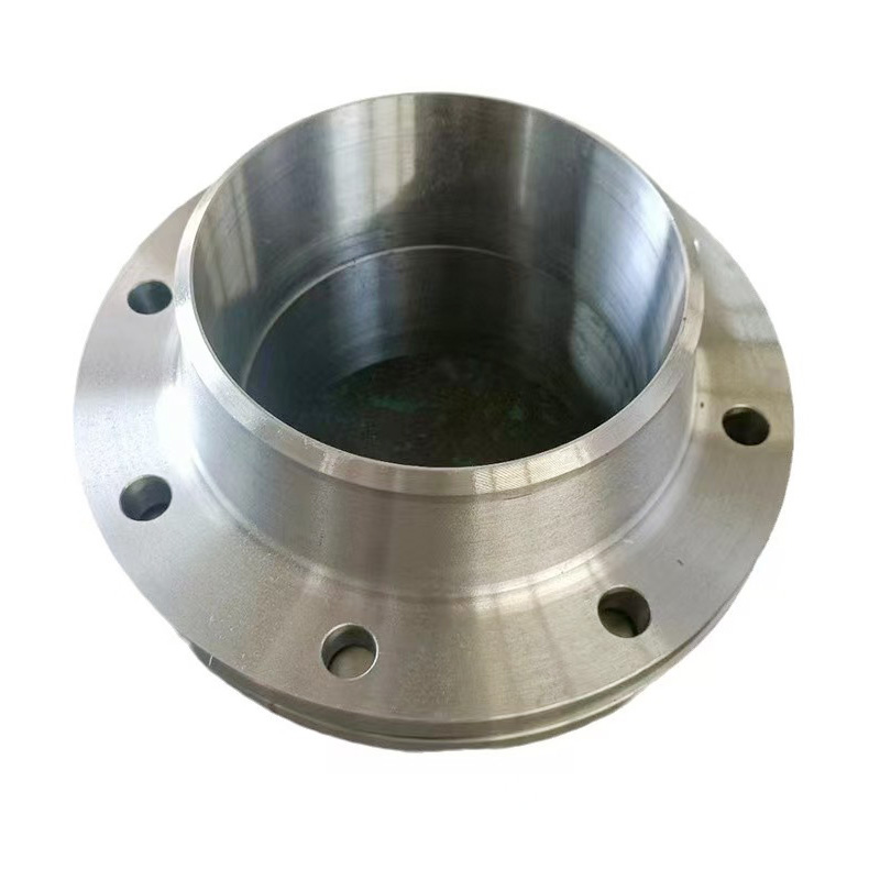
AWeld Neck Flange (WN Flange)is a type of piping flange designed to be welded to a pipe or ...
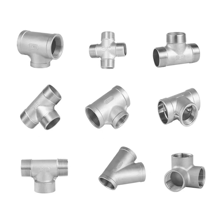
Socket fittings are essential components in piping systems, designed to connect, branch, or...
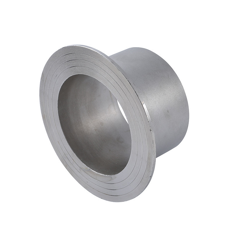
Welding ring is a commonly used metal ring component in pipeline connection or equipment do...
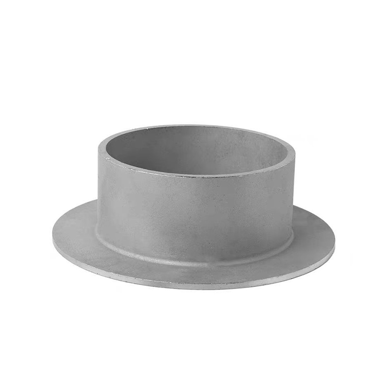
Welding ring is a pipe fitting used for pipeline connection. The following is its detailed ...