Installation Best Practices for Eccentric Reducer Heads
2025-12-03 13:35:49
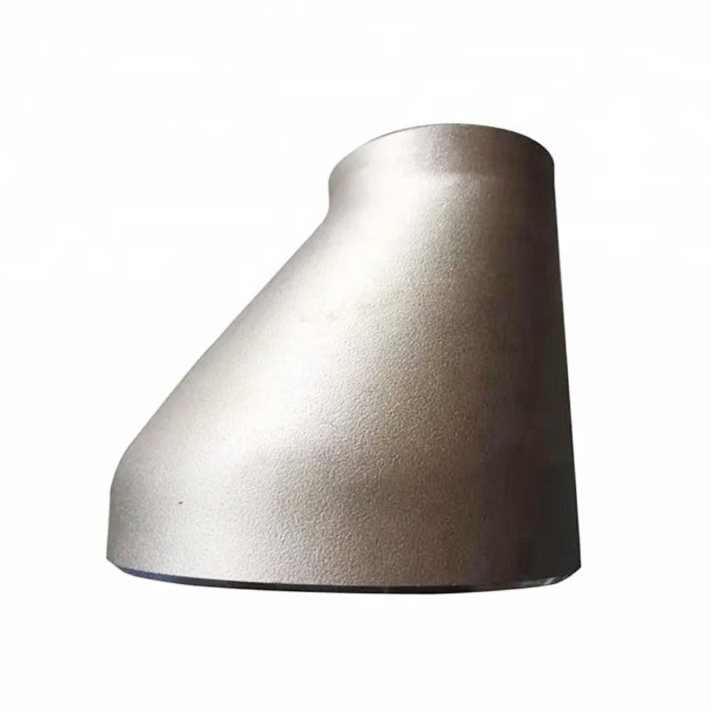
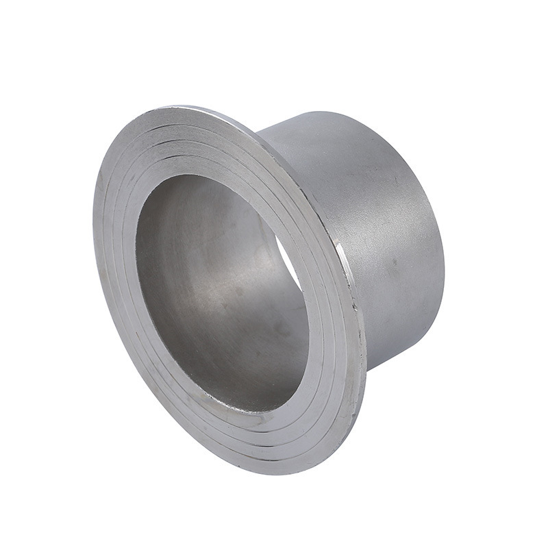
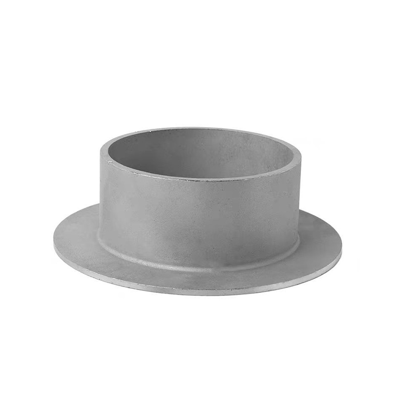
An Eccentric Reducer Head is essential in industries where stable fluid movement, controlled drainage, and precise flow transitions are required. Its asymmetric design enables consistent leveling in horizontal piping, prevents fluid accumulation, and minimizes turbulence during diameter reduction. Because this type of reducer is widely used in chemical lines, process equipment, and drainage-intensive systems, a correct installation approach directly determines its long-term reliability.
For teams working on industrial piping integration or for a manufacturer managing production and bulk supply, following proven installation methods ensures structural safety, stable flow, and maximum operational efficiency.

1. Key Function of Eccentric Reducer Heads
The off-center geometry of an eccentric reducer ensures that one side remains perfectly aligned with the main pipeline. This unique shape is engineered to:
·Keep air from getting trapped in liquid pipelines
·Maintain consistent fluid levels through horizontal sections
·Deliver smooth flow transitions without generating excess turbulence
The reducer’s functionality heavily depends on accurate orientation and flawless integration.
2. Selecting the Correct Orientation
Correct placement is the first and most important step in installing an Eccentric Reducer Head.
Flat-Top Configuration
Applied when:
·Preventing air entrapment is critical
·Complete liquid drainage from the upper section is required
·Uniform system flow must be maintained
Here, the straight edge of the reducer aligns with the upper surface of the pipe.
Flat-Bottom Configuration
Used when:
·Solids, sediment, or slurry must avoid settling
·Drainage at the lower part of the system is essential
This orientation ensures unhindered movement of solid-bearing fluids.
3. Preparing Surfaces for Installation
Proper preparation ensures a durable connection and minimizes future failures.
Thorough Cleaning
Remove contaminants such as:
·Surface rust
·Grease and cutting fluids
·Metal dust or debris
Clean, smooth surfaces promote strong weld bonding.
Dimensional Verification
Confirm that the reducer matches the pipe’s dimensions—diameter, wall thickness, and schedule—before welding begins. Even small deviations may lead to joint stress.
Check for Production Imperfections
Reducer heads arriving from manufacturer production batches should be inspected for dents, uneven edges, or dimensional inconsistencies.
4. Alignment and Fit-Up Accuracy
Proper alignment supports both structural stability and flow quality.
Maintain a Consistent Root Gap
A uniform welding gap ensures complete penetration and avoids internal obstructions.
Ensure Axial and Radial Precision
Misalignment can cause:
·Flow disturbances
·Excess noise or vibration
·Premature stress failure at joints
Fit-up tools or pipe clamps help maintain accurate positioning before welding.
5. Welding Techniques for Eccentric Reducer Heads
Welding is one of the most critical steps, as it forms the permanent structural bond between the reducer and the pipe.
Choose the Appropriate Welding Process
Depending on the material and thickness, common choices include GTAW, SMAW, and GMAW.
Heat Input Management
Controlled heat application prevents:
·Distortion of the reducer head
·Weakening of the heat-affected zone
·Warping that disrupts flow alignment
Smooth Root and Fill Layers
Start with a clean, consistent root pass to ensure penetration. Add fill passes evenly to avoid creating internal edges that may disrupt fluid movement.
Avoiding Internal Protrusions
Any irregularity inside the reducer can disturb flow, particularly in high-velocity systems. Smoother interior welds boost hydraulic efficiency.
6. Structural Support and System Stress Relief
To ensure that the Eccentric Reducer Head can withstand long-term operation, proper support is mandatory.
Install Adequate Piping Supports
Reducers should never bear the pipe’s weight. Supports prevent sagging and reduce stress at the weld seam.
Thermal Expansion Allowance
Pipeline materials expand and contract, especially in hot or high-pressure environments. Proper spacing and flexibility reduce stress accumulation.
Vibration Control
Mechanical vibration can accelerate fatigue failure. Additional bracing is recommended when reducers are installed near pumps, compressors, or high-velocity flow points.
7. Inspection and Final Testing
Before the system is commissioned, several quality checks must be performed.
Visual Examination
Inspect welds for issues such as:
·Undercut
·Incomplete fusion
·Bead irregularity
·Joint misalignment
Non-Destructive Testing (NDT)
Depending on system safety requirements, testing may include:
·Dye penetrant
·Ultrasonic scans
·Radiographic imaging
Pressure and Leak Testing
Hydrostatic testing verifies that the reducer head can endure operational pressures without leakage or deformation.
8. Frequent Installation Errors to Avoid
Typical mistakes that affect long-term performance include:
·Installing the flat side incorrectly (top vs. bottom)
·Excessive heat input during welding
·Allowing the reducer to distort after welding
·Using mismatched filler metal
·Neglecting support structures
·Leaving internal weld beads that obstruct flow
Preventing these errors results in a safer, more efficient system.
Conclusion: Ensuring Reliable Eccentric Reducer Head Performance
A properly installed Eccentric Reducer Head enhances drainage behavior, stabilizes pressure transitions, and reinforces the reliability of industrial pipeline systems. Whether the installation is carried out in-field or the components originate from a manufacturer offering consistent production and bulk supply, following the correct procedures ensures dependable operation for years to come. Careful orientation, precise welding, robust support, and thorough inspection together form the foundation of a long-lasting and high-performance reducer head installation.
References
GB/T 7714:Lippold J C, Kotecki D J. Welding metallurgy and weldability of stainless steels[M]. 2005.
MLA:Lippold, John C., and Damian J. Kotecki. Welding metallurgy and weldability of stainless steels. 2005.
APA:Lippold, J. C., & Kotecki, D. J. (2005). Welding metallurgy and weldability of stainless steels (p. 376).
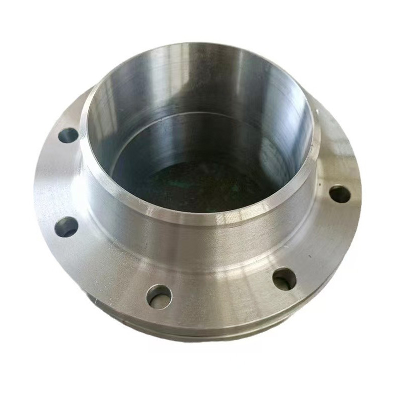
AWeld Neck Flange (WN Flange)is a type of piping flange designed to be welded to a pipe or ...
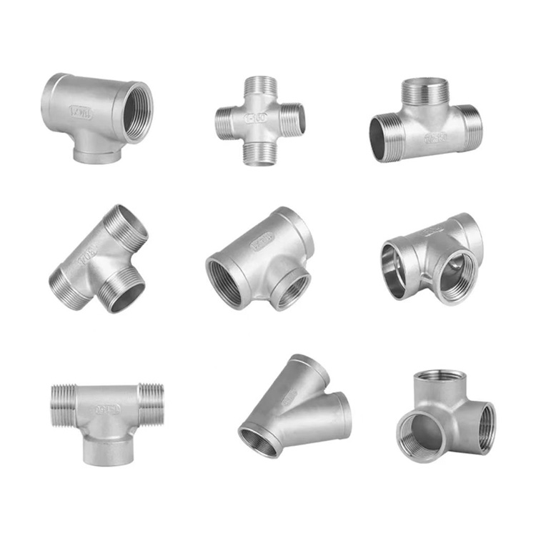
Socket fittings are essential components in piping systems, designed to connect, branch, or...
Welding ring is a commonly used metal ring component in pipeline connection or equipment do...
Welding ring is a pipe fitting used for pipeline connection. The following is its detailed ...